
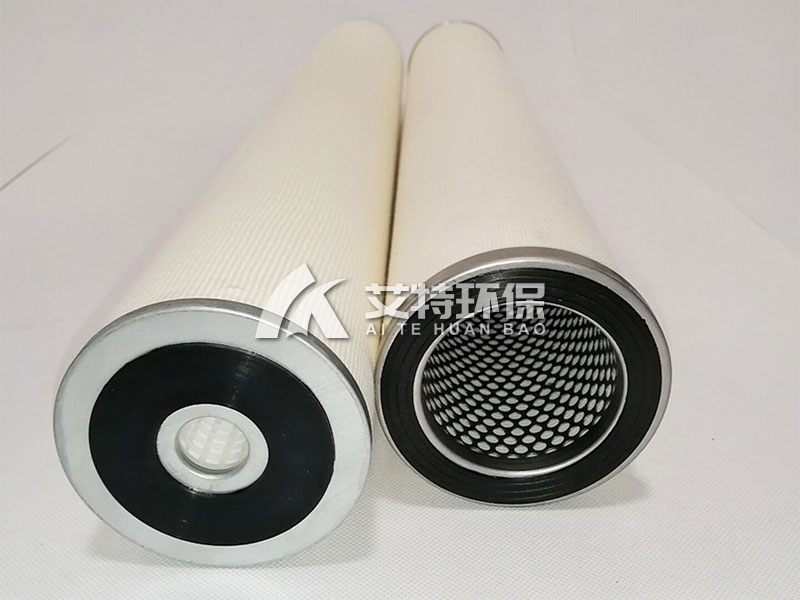
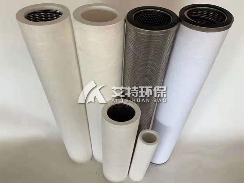
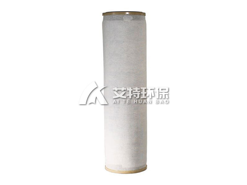
Coalescence separation filter element natural gas filter layer kerosene pipeline filter oil-water separation coalescence filter element.Oil-water separation filter element is mainly designed for oil-water separation, it contains two kinds of filter element, namely: poly filter element and separation filter element.
1. Product Introduction
The Coalescence-Separation Filter Element is a specialized filtration component designed primarily for oil-water
separation applications. The system incorporates two distinct filter element types working in sequence: the coalescer
filter element and the separation filter element. This dual-element design delivers superior removal of both solid
particulates and emulsified/free water from hydrocarbon fluids, natural gas, and other process streams.
Commonly deployed in pipeline gas transmission devices, fuel storage systems, and industrial lubrication circuits,
these filter elements ensure product quality, protect downstream equipment from corrosion and wear, and maintain
system efficiency across demanding operating conditions.
2. Technical Specifications
Parameter Specification
Material Stainless steel (housing and support components)
Filter element form Pleated (folding) design for maximum surface area
Primary function Oil-water separation (coalescing + separation)
Applicable media Lubricating oil, natural gas, crude oil, kerosene, cutting fluid, grinding oil
Operating temperature Up to 60°C (standard); high-temperature options available
Maximum working pressure differential 5 MPa
Filtration precision 1 – 20 μm (multiple grades available)
Connection diameter Customizable per application
Chemical resistance Alkali-resistant, acid-resistant, low-temperature resistant, high-temperature resistant
Raw water pressure 5 kg/cm² (standard configuration)
Flow direction Outside-in (contaminants collected on exterior surface)
3. Key Performance Characteristics
3.1 Dual-Stage Separation Architecture
The coalescence-separation system combines two complementary filtration stages in a single housing:
· Coalescer Stage (Primary): Captures solid particles and coalesces microscopic water droplets into larger, separable
water beads
· Separator Stage (Secondary): Utilizes hydrophobic media to block residual free water while allowing clean oil to pass freely
This staged approach achieves far superior water removal compared to single-stage filters.
3.2 High-Efficiency Particle Filtration
The pleated stainless steel coalescer element provides large filtration area within a compact footprint, effectively capturing:
· Coarse particles (settle immediately and drain via sump valve)
· Fine particles (intercepted by the filter media matrix)
· Rust, scale, and process contaminants
3.3 Superior Water Coalescence Performance
The coalescer medium is engineered with specific surface chemistry and pore structure that:
· Promotes collision and adhesion of microscopic water droplets
· Accelerates droplet growth from <1μm to >200μm
· Facilitates gravity-based separation in the settling chamber
3.4 Reliable Hydrophobic Separation
The separator element features a proprietary hydrophobic (water-repellent) surface treatment:
· Oil passes through freely with minimal pressure drop
· Free water is blocked, coalesces on the element surface, and drains to the collection sump
· Prevents re-emulsification of separated water
3.5 Robust Chemical Resistance
Stainless steel construction and specially selected media provide resistance to:
· Alkaline and acidic process streams
· Low and high temperature extremes
· Corrosive components in crude oil and natural gas
4. Working Principle – Detailed Process Flow
Stage 1: Inlet Flow Distribution
Contaminated oil or gas enters the lower section of the filter housing through the inlet pipe. The flow is distributed evenly
across the filter elements to maximize media utilization and prevent channeling.
Stage 2: Coalescer Stage (Primary Filtration)
The fluid flows through the coalescer filter element from outside to inside. During this passage:
· Coarse particles (≥20μm) settle immediately under gravity and are removed via the bottom drain valve
· Fine particles are intercepted within the depth of the filter media
· Emulsified water droplets (<1μm) are captured on the coalescing fibers, where they collide, coalesce, and grow into
large water beads (>200μm)
· Solid impurities are retained on the outer surface and within the media structure
Stage 3: Gravity Settling
Most coalesced water droplets, now large enough to overcome fluid drag forces, separate by gravity and settle into the
collection sump at the bottom of the housing. This gravity separation removes the majority of free water before the fluid
reaches the secondary stage.
Stage 4: Separator Stage (Secondary Filtration)
The partially dehydrated oil then passes through the separation filter element (also outside-in). The separator media is
manufactured with strong hydrophobic properties:
· Clean oil passes through freely to the outlet
· Residual free water is blocked on the element surface, coalesces into larger droplets, and flows downward into the
precipitation tank
· Ultra-fine particulates are captured as a secondary benefit
Stage 5: Clean Fluid Collection & Discharge
Finally, the clean, dehydrated oil is collected by the filter element tray, flows through the outlet pipe, and exits the coalescence
separator for downstream use or storage.
Stage 6: Monitoring & Maintenance Alert
As the volume of processed fluid increases, contaminants deposited on the filter elements cause the differential pressure
to rise. When the pressure differential reaches 0.15 MPa, it indicates that the coalescer element is blocked and should be
replaced. For separator elements, replacement is typically required when similar pressure drop thresholds are reached or
during scheduled maintenance.
5. Applications
· Natural Gas Transmission Pipelines – Removal of water, solid particulates, and hydrocarbon condensates to protect
compressors, valves, and metering equipment
· Kerosene & Aviation Fuel Systems – Water removal to meet fuel quality specifications and prevent microbial growth
· Petrochemical Refineries – Separation of water from hydrocarbon streams in processing units
· Lubrication Oil Circuits – Removal of water contamination from circulating oil systems in turbines, compressors,
and gearboxes
· Hydraulic Systems – Elimination of emulsified water to prevent corrosion, reduce fluid degradation, and extend component
life
· Process & Industrial Fluid Filtration – Cutting fluids, grinding oils, and other water-contaminated industrial fluids
6. Maintenance & Operation Guidelines
1. Differential Pressure Monitoring – Install a differential pressure gauge across the filter housing. Replace the coalescer
element when differential pressure reaches 0.15 MPa (or as specified for your application).
2. Regular Drainage – Drain accumulated water from the sump/collection tank at scheduled intervals or continuously via
automatic drain valves.
3. Element Replacement Protocol – Replace both coalescer and separator elements according to manufacturer
recommendations or when differential pressure indicates blockage. Always replace seals during element change-out.
4. Water Quality Testing – Periodically test outlet fluid for water content to verify separator performance and identify media
breakthrough early.
5. Storage of Spare Elements – Store in original packaging in a dry, dust-free environment away from direct sunlight and
chemicals.
7. FAQ (Frequently Asked Questions)
Q1: What is the difference between the coalescer and separator filter elements?
A: The coalescer element captures solid particles and coalesces microscopic water droplets into large water beads.
The separator element uses hydrophobic media to block free water while allowing clean oil to pass. They work as a sequential
two-stage system for optimal water removal.
Q2: What filtration precision can this system achieve?
A: The system offers precision grades from 1μm to 20μm, depending on the selected element rating. The coalescer captures
particles and coalesces droplets, while the separator blocks residual water and polishes the fluid.
Q3: What is the maximum operating temperature for these filter elements?
A: The standard configuration is rated up to 60°C. For higher temperature applications (up to 120°C+), we offer specialty media
and seal materials. Please specify your temperature requirements when ordering.
Q4: At what differential pressure should the filter elements be replaced?
A: The coalescer element should be replaced when the pressure differential reaches 0.15 MPa (1.5 bar). The separator element
typically follows the same threshold. Monitor the pressure gauge and replace when the recommended change-out value is
reached.
Q5: Can these filter elements be used for natural gas applications?
A: Yes. They are specifically designed for pipeline gas transmission systems to remove water, solid particles, and hydrocarbon
liquids from natural gas streams, protecting compressors and downstream equipment.
Q6: Are the filter elements washable and reusable?
A: No. The coalescence and separation media are not washable. Attempting to clean them will damage the fiber structure and
surface treatment, permanently reducing efficiency. Always replace with new elements.
Q7: What fluids are compatible with these filter elements?
A: Compatible fluids include lubricating oils, natural gas, kerosene, crude oil, cutting fluids, grinding oils, and various
hydrocarbon-based fluids. For aggressive chemicals or non-standard fluids, please consult our technical team for compatibility
verification.
Q8: What is the flow direction through the filter elements?
A: The flow direction is outside-to-in for both coalescer and separator elements. This design ensures contaminants are
captured on the exterior surface, facilitating gravity settling and easier maintenance.
Q9: How does the hydrophobic separator work?
A: The separator media has been treated to be water-repellent (hydrophobic) while remaining oil-permeable. Water droplets
are blocked on the surface, coalesce into larger beads, and drain downward to the collection sump. Clean oil passes through
freely.
Q10: What causes the pressure differential to rise?
A: Pressure differential increases as the coalescer element captures solid contaminants and the separator element blocks
water. When the pressure drop reaches 0.15 MPa, the coalescer is considered fully loaded and requires replacement.
Q11: Can these filter elements be used for both liquid-liquid and gas-liquid separation?
A: Yes. The dual-stage design is effective for both liquid-liquid (oil-water) separation and gas-liquid
(natural gas-water/hydrocarbon) separation applications.
Q12: What are the standard connection sizes for inlet and outlet?
A: Connection sizes vary by application and flow rate requirements. Standard configurations typically use 1-inch to 4-inch
connections, but custom sizes are available upon request. Please specify your piping specifications.
Q13: How should I store spare filter elements?
A: Store in original packaging in a cool, dry, dust-free environment (10–30°C, <60% RH). Avoid exposure to UV light, extreme
temperatures, and chemicals. Properly stored elements maintain performance for up to 3–5 years.
Q14: Can I replace only the coalescer element without replacing the separator?
A: While the coalescer typically requires more frequent replacement, we recommend replacing both elements simultaneously
to ensure balanced performance and avoid premature separator clogging from increased contaminant load.
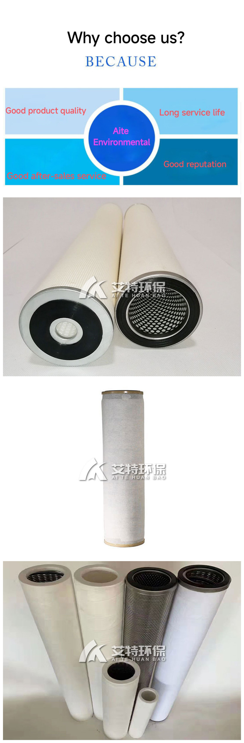
PCHG-536 Natural gas filter element
Similar ProductsVIEW MORE >
WhatsApp / Wechat: +8613273719759
Factory Address: Zhengshang Navigation Square, South Hanghai Road, Erqi District, Zhengzhou City, Henan Province P.R.China.


 Export01@aiteeps.com
 ++8613273719759
